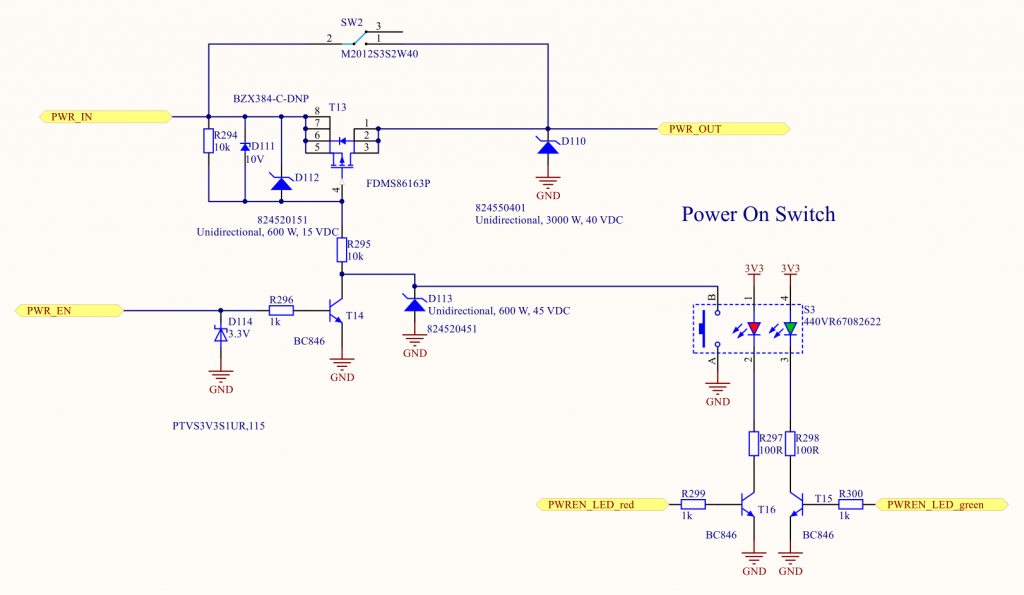


P CHANNEL FET PLUS
Anyway, what followed from that was a statement that an N-channel device plus a small transistor can not be made to perform the same function on the high side as a P-channel device can. Realistically P-channel devices suck when compared against similar N-channel FETs and that is part of the reason people even bother to go about designing boost circuits to allow all N-channels devices to be used in a bridge. What was said was that given the IRL520 as an N-channel FET to compare to, a P-channel device of the same characteristic ratings would generally be applied for the purpose of switching high-side. No one but you has said power HAS to be switched high side. The MOSFET exhibited a drain current density of 1.7 mA/mm. Zoomkat you are reading more into my reply than I put there in your attempt to show how it can all (?) be done low-side. A normally-off inversion p-channel metal-oxide-semiconductor field-effect transistor (MOSFET) with a nitrogen (N)-doped diamond body deposited using microwave plasma-enhanced chemical vapor deposition (MPECVD) was fabricated. This requirement was not included in the origional post. Pretty much a restatement of the same potentially flawed assumptions based on the assumption that the power has to be high side switched. I guess I ought to test that idea, but once again, I’ll consider any suggestion thoroughly. On the other hand, as I was writing this, it occured to me that I might not need a FET of any sort. By using the N-channel FET, I have done the opposite: The LED is on unless the switch is closed, which would mean that BOTH switches must be closed. Each whisker is hooked to a different FET, so current will flow from either one, and light an LED when either switch is pressed. Thus I thought that I could use a p-channel FET such that current only flowed when the switch was closed. What I set up was that the sensors were pulled high, and would go low when the switch is closed. Since I am more I/O line limitted than anything else, saving two lines is valuable.

For both the left and the right side, if either sensor trips, I don’t actually need to know which one it is. Therefore, I don’t need four different I/O lines for these sensors, but instead only need two. Now, I have some pretty serious brainpower on this system, so I know that I can only run into something when I’m going forwards. I have four whiskers on a robot, two in front, and two in back. Hence, we need to apply a proper negative voltage to turn ON MOSFET. The MOSFET is a power electronics switch that will turn ON when the proper voltage is applied to the gate terminal. I’m new to electronics, so some of the jargon went over my head, but let me describe what I am doing, perhaps somebody can suggest a better solution: Here, we will simulate IRF9540 available in proteus.


 0 kommentar(er)
